me three.Eft37 wrote:me too
48mm Spree BBK(taz)
Moderator: Moderator
-
Trafficjamz

- CBR1000RR

- Posts: 5353
- Joined: Tue Jul 14, 2009 7:53 pm
- Location: Eastlake, MI
- Contact:
Re: 48mm Spree BBK(taz)
new best 1/8th mile time 9.647 seconds @67.155 mph 310lbs total weight
-
tazland001

- Board Supporter
- Posts: 1333
- Joined: Thu Apr 30, 2009 11:46 pm
Re: 48mm Spree BBK(taz)
You guys crack me up. 
Can you guys actuall believe there is a 48mm BBK for the spree. Its like a dream come true. Man someone should be buying me a steak dinner or somethin.
Taz
Can you guys actuall believe there is a 48mm BBK for the spree. Its like a dream come true. Man someone should be buying me a steak dinner or somethin.
Taz
-
eliteguy50
- CBR1000RR
- Posts: 4219
- Joined: Thu Mar 05, 2009 9:02 pm
- Location: Iowa, USA
Re: 48mm Spree BBK(taz)
You come out here to Iowa and I will let you pick out what steak you want (hoof fresh).tazland001 wrote:You guys crack me up.
Can you guys actuall believe there is a 48mm BBK for the spree. Its like a dream come true. Man someone should be buying me a steak dinner or somethin.
Taz
motormike wrote:Errands become adventures.
-
spree-rider
- Elite
- Posts: 693
- Joined: Tue Nov 03, 2009 8:24 pm
- Location: Burien, WA
Re: 48mm Spree BBK(taz)
Haha taz. you crack me up. Well, if you come to Burien i will have a staek bb-qed to your perfection waiting for you for what you have done on this foroum.tazland001 wrote:You guys crack me up.
Can you guys actuall believe there is a 48mm BBK for the spree. Its like a dream come true. Man someone should be buying me a steak dinner or somethin.
Taz
86 spree
sb 50 intake and reeds
3.00x10 rear tire
waxed
99Polaris indy 700
harliquim paint
2" bar riser
lefty throttle
ice scratchers
SLP tri keel skis
ported
high compression head
chrome low windshield
mountain bar
Xtra-10
I ALWAYS KEEP ONE ROLLED
sb 50 intake and reeds
3.00x10 rear tire
waxed
99Polaris indy 700
harliquim paint
2" bar riser
lefty throttle
ice scratchers
SLP tri keel skis
ported
high compression head
chrome low windshield
mountain bar
Xtra-10
I ALWAYS KEEP ONE ROLLED
-
CrazyRobCustoms
- Noob

- Posts: 2
- Joined: Wed Apr 28, 2010 8:02 pm
Re: 48mm Spree BBK(taz)
Anyone know taz's ebay store? Is it chop chop? Thanks!
-
eliteguy50
- CBR1000RR
- Posts: 4219
- Joined: Thu Mar 05, 2009 9:02 pm
- Location: Iowa, USA
Re: 48mm Spree BBK(taz)
Yes, http://myworld.ebay.com/ebaymotors/chopchop*123/CrazyRobCustoms wrote:Anyone know taz's ebay store? Is it chop chop? Thanks!
motormike wrote:Errands become adventures.
-
martynkim
- Board Supporter
- Posts: 2899
- Joined: Tue Jan 05, 2010 10:22 pm
- Location: Tacoma, Washington
Re: 48mm Spree BBK(taz)
Me four, Head is already being bored 
Need parts? Parting out Spree Aero and Elite!
What people share about buying from me http://www.hondaspree.net/phpBB3/viewto ... =1&t=15559
PM me with your needs Cheap Parts
What people share about buying from me http://www.hondaspree.net/phpBB3/viewto ... =1&t=15559
PM me with your needs Cheap Parts


Re: 48mm Spree BBK(taz)
I'm sure a variator can be made that will fit; but it will be small compared to the Elite. If you look at the later Spree steel pulley inner, that's essentially your package size. From the prior work I did with the steel pulley, the variator "throw" can only be maximum 0.125" from stock belt position to full out before you run out of pulley diameter on the outside pulley. I think the Elite throw is probably at least twice that.
The castings aren't undoable, but they're expensive up front, even as a lost-wax process, which I think is about the cheapest way to do small runs like this given the features you'd need on the outer variator half. And you'd need two of them, b/c I think it would be most cost-effective to cast both the pulley face (typically cast) and variator back (typically stamped) than to pay for the variator back stampings.
You'd need a ramp plate, which is a stamping with a couple of it's own dies. It would be less expensive up front if you could design around an existing ramp plate and trim it to size on a lathe/other, rather than have to buy the dies for this. Or made the ramp plate a perfectly flat circle, which might package thinner anyway.
It would require unique rollers that are quite a bit smaller than the Elite's to keep the package thin. Really not a big deal, but depending on the package size might need to be made out of something dense, like tungsten, due to small size. Probably a saw cut of some stock material.
You'd want to tune the rear spring too on the clutch. Not sure if that's an off-the-shelf part. Custom springs typically aren't that outrageous.
The rest of the stuff, bearings, sleeves, screws, seals, are standard items you can design around.
Sounds interesting. I'm waiting to see how it all plays out.
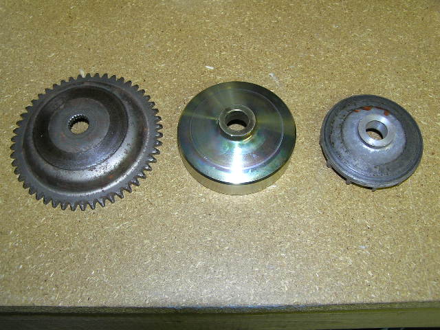
Actually, I think you could make the variator back perfectly flat too... As I'm thinking about it, I bet I can draft up a design that can be adapted from the stock Spree steel pulley, using machine tools like a lathe and mill... let me noodle on that a bit. Starting with the center one shown here:
The castings aren't undoable, but they're expensive up front, even as a lost-wax process, which I think is about the cheapest way to do small runs like this given the features you'd need on the outer variator half. And you'd need two of them, b/c I think it would be most cost-effective to cast both the pulley face (typically cast) and variator back (typically stamped) than to pay for the variator back stampings.
You'd need a ramp plate, which is a stamping with a couple of it's own dies. It would be less expensive up front if you could design around an existing ramp plate and trim it to size on a lathe/other, rather than have to buy the dies for this. Or made the ramp plate a perfectly flat circle, which might package thinner anyway.
It would require unique rollers that are quite a bit smaller than the Elite's to keep the package thin. Really not a big deal, but depending on the package size might need to be made out of something dense, like tungsten, due to small size. Probably a saw cut of some stock material.
You'd want to tune the rear spring too on the clutch. Not sure if that's an off-the-shelf part. Custom springs typically aren't that outrageous.
The rest of the stuff, bearings, sleeves, screws, seals, are standard items you can design around.
Sounds interesting. I'm waiting to see how it all plays out.
Actually, I think you could make the variator back perfectly flat too... As I'm thinking about it, I bet I can draft up a design that can be adapted from the stock Spree steel pulley, using machine tools like a lathe and mill... let me noodle on that a bit. Starting with the center one shown here:
Admin, Hondaspree.net
Buy air filters and gaskets here (Ebay): http://stores.ebay.com/noiseguysstore
Buy air filters and gaskets here (Amazon): www.amazon.com/shops/spreepower
Buy a t-shirt here: https://teespring.com/stores/spree-powersport-products
Buy air filters and gaskets here (Ebay): http://stores.ebay.com/noiseguysstore
Buy air filters and gaskets here (Amazon): www.amazon.com/shops/spreepower
Buy a t-shirt here: https://teespring.com/stores/spree-powersport-products
Re: 48mm Spree BBK(taz)
OK. Here's a Spree variator that someone should be able to make from off-the-shelf stuff, with a lathe, welder, grinder, and some balancing tools. No special molds / dies required. Please excuse the poor drawings.
It's not dimensioned: x is the diameter for clearance to crank (probably +.001" to crank size) and y is arbitrary, though some of the y need to be bigger for clearance to rotate. You can figure it out.
First image is the stock pulley. You'll need a lathe. Machine out the inside, enlarge center hole, remove outer boss. Drill and tap for screws to attach rear cover.
Second shows the blow-up. Ramp plate is not well detailed. Note flat variator back, of thin sheet steel. Simple to fabricate. Center bushing can be off the shelf or made on lathe. Weights could be ball bearings or rollers.
Last, detail of ramp plate. Since the variator outer is simple, the ramp plate is more complicated. It needs to have channels to hold the weights in place. Not sure if this will work without channel guides on the variator outer, but since the throw is short (1/8") if the balls are larger than that (say 1/4") then they shouldn't be able to fall out. I think you make the guide from steel U-channel, then weld it together in the cross-shape, bent back. You will want to balance (probably dynamically) this part when you're done, as it needs to rotate fast. The cross-design is arbitrary; it could be a three-channel design as well. I think it would need to be tapered as you go out (thicker in the center,) but it's beyond me how much or what it would look like complete.
ERROR IN DRAWING: That center hole should be x, not y. Otherwise it won't work. And for that matter, all the variator back needs to do is keep the ramp plate inside the variator outer. Center hole could be larger, as needed.
One thing I forgot to design are the guide sliders for the ramp plate (the ramp plate would not rotate with crank as shown.) You could weld fins to the variator outer and let the ramp plate slide on that. You would then need to balance the variator outer as well. Probably should do this with the whole thing assembled and without the balls.
This can all be made from off-the-shelf parts and materials, but will require some skills with machine tools. But there's no expensive one-off tooling to buy.
If anyone builds this, I'd like to see it. Have fun!
It's not dimensioned: x is the diameter for clearance to crank (probably +.001" to crank size) and y is arbitrary, though some of the y need to be bigger for clearance to rotate. You can figure it out.
First image is the stock pulley. You'll need a lathe. Machine out the inside, enlarge center hole, remove outer boss. Drill and tap for screws to attach rear cover.
- Modifications to stock pulley
- stock pulley.jpg (65.57 KiB) Viewed 3736 times
- Variator blow up
- modified pulley.jpg (63.7 KiB) Viewed 3735 times
ERROR IN DRAWING: That center hole should be x, not y. Otherwise it won't work. And for that matter, all the variator back needs to do is keep the ramp plate inside the variator outer. Center hole could be larger, as needed.
- Complicated ramp plate
- variator ramp.jpg (29.03 KiB) Viewed 3736 times
This can all be made from off-the-shelf parts and materials, but will require some skills with machine tools. But there's no expensive one-off tooling to buy.
If anyone builds this, I'd like to see it. Have fun!
Admin, Hondaspree.net
Buy air filters and gaskets here (Ebay): http://stores.ebay.com/noiseguysstore
Buy air filters and gaskets here (Amazon): www.amazon.com/shops/spreepower
Buy a t-shirt here: https://teespring.com/stores/spree-powersport-products
Buy air filters and gaskets here (Ebay): http://stores.ebay.com/noiseguysstore
Buy air filters and gaskets here (Amazon): www.amazon.com/shops/spreepower
Buy a t-shirt here: https://teespring.com/stores/spree-powersport-products
-
tazland001
- Board Supporter
- Posts: 1333
- Joined: Thu Apr 30, 2009 11:46 pm
Re: 48mm Spree BBK(taz)
Thanks for the response noise. I was hoping someone was pondering some of my questions. I will read the thread after my algebra test tonight so I can fully absorb all of the material.
Taz
Taz
-
wikked_spree57
- Elite
- Posts: 980
- Joined: Thu Aug 16, 2007 6:50 am
- Location: Bridgeport, MI
- Contact:
Re: 48mm Spree BBK(taz)
Not to Bash on the Spree breakthroughs, but I would be very interested in seeing this type of thing for the Razz, at least gears and a 48mm as well. I'm a Razz owner and I was impressed by the durability of the BBK (I was running on the oil pump alone for lubrication and was running WOT for 10+ miles after 125-150 miles of break-in) and the extra punch it put in what I long though was a terd of a scooter.
My first guess is there are not enough interested parties for the Yamaha side of the park, but the Razz gearing is not that complicated. Most of the gears are redily accessible under the trans cover. Only pain is these use a wet clutch with a chain.
Marc, I'm seriously impressed to the point where I'm looking for a Spree just to see these parts work. I'd love to see my fiance's Razz I bought her slap 45MPH too.
If I find a Spree by the release date of the 48 kit, Me five on that. I'll be in for a pipe and gears as well, AND the 44mm for the Razz.
I never thought there would be much hope for the Spree, till you joined this forum. Now I think I might actually be able to build a sleeper and nobody around here knows of these parts yet. They think the Sprees are still slow. I can't wait to see jaws drop!
So is the reason I haven't seen much for the Razz due to lack of interest? There are more of those things around here than any other scooter, even the China bikes. So I was curious, I'd like to sell the kits locally. I work on a couple hundred scooters a year, and since the 44 for the Razz I have never used stock parts since. I'm that impressed. And the price is killer!
1994 BMW 525i 5 speed BEAMER TIME
1983 Yamaha XC 180 - Bought barn fresh in mint condition and 254 miles. Best bike I ever owned
1983 Yamaha XC 180 - Bought barn fresh in mint condition and 254 miles. Best bike I ever owned
Re: 48mm Spree BBK(taz)
I'm stepping out of line, I ended up being impatient and went with his 44mm kit and a 50mm for my SA50.
-
mustangwagz

- Elite
- Posts: 483
- Joined: Sun Mar 21, 2010 9:10 pm
- Location: Western, PA
Re: 48mm Spree BBK(taz)
Is the 48mm kit gonna be easier to break in than the 44? lol
-Zac
1981 HD-Ironhead Sporty. 1000cc, 4 speed, drag pipes, and drag bars.. (chic/cop magnet)
72 Rupp Roadster 2 (aka. RUMP ROASTER!!)
05 vinson
78 bronco (Log skiddin Hog!!)
1981 HD-Ironhead Sporty. 1000cc, 4 speed, drag pipes, and drag bars.. (chic/cop magnet)
72 Rupp Roadster 2 (aka. RUMP ROASTER!!)
05 vinson
78 bronco (Log skiddin Hog!!)
Re: 48mm Spree BBK(taz)
It was more of a 'price is right' situation.
-
jsun3thousand
- BMX

- Posts: 31
- Joined: Tue Apr 27, 2010 1:54 am
Re: 48mm Spree BBK(taz)
I want in on this action.