Page 2 of 2
Re: Electronic 2 Pin LED Flasher Test
Posted: Sun May 08, 2022 11:53 am
by mousewheels
Major Component Identification
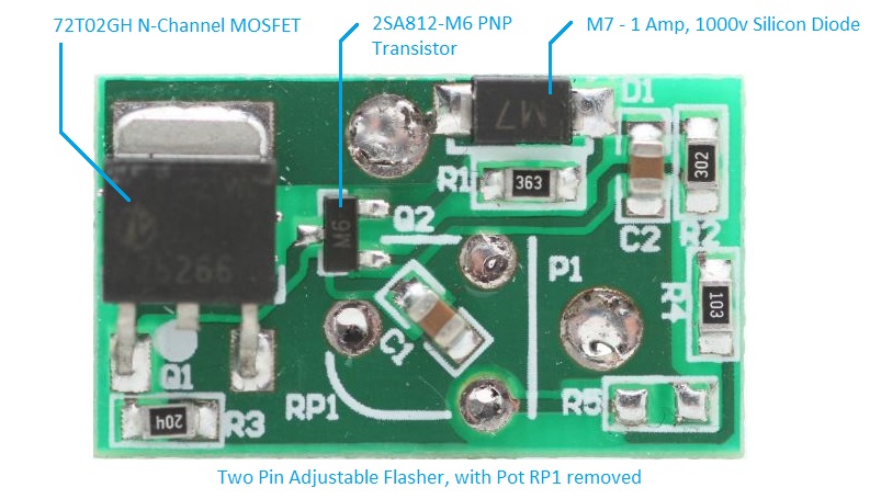
- Board_w_pot_removed_sm.JPG (115.74 KiB) Viewed 1954 times
Schematic
The board layout and components look completely different from the Fixed flasher torn down earlier.
However, comparing schematics, the boards are very similar in design.
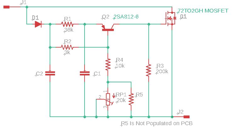
- Adjustable_Flasher_Schematic.JPG (33.93 KiB) Viewed 1954 times
Schematic - PCB Check
Waiting for parts to arrive gave time to check out the schematic.
If the schematic is correct, then laying out a PCB should re-create
a board resembling the original PCB.
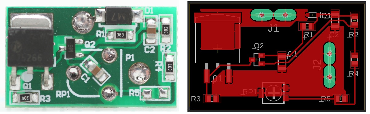
- Orig_PCB_vs_Layout_from_Traced_Schematic.jpg (143.71 KiB) Viewed 1954 times
Re: Electronic 2 Pin LED Flasher Test
Posted: Sat Jul 23, 2022 1:51 am
by mousewheels
LEDs
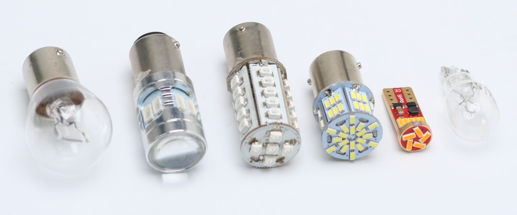
Here's what has been tested:
- The Tail/Stop lamp is out of scope for the Flasher test. Notable is it's seller spec'd 5v-24v operation.
- To my eye, the right most T10 lamp was the brightest, followed by the White LED. The Amber LED in the center is the weakest.
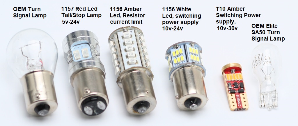
- Lamp_Comparison_1a.jpg (126.79 KiB) Viewed 1712 times
- Lamp_Comparison_2.jpg (76.16 KiB) Viewed 1712 times
Re: Electronic 2 Pin LED Flasher Test
Posted: Sat Jul 23, 2022 2:11 am
by mousewheels
Switching Regulator LEDs
Upon varied input voltage, the LEDs with internal switching regulators performed to their low voltage spec. I only tested them with flashers to 15v, but ran up to 20v on the lamps alone. In our scooters, the regulator/battery should keep the voltage to around 14.2 max.
Beyond the low end of the spec, LEDs with switching regulators light level drops off very quickly, then extinguishes.
Resistor current regulated LED
The lone LED with only a resistor to limit current dropped off gradually as expected until below the forward voltage of the LEDs.
An interesting behavior was below a certain voltage a partial turn off was observed.
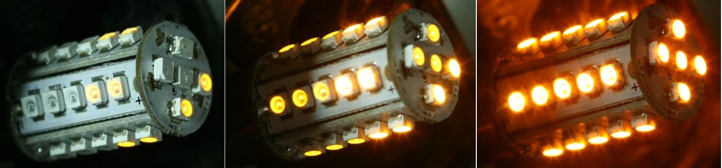
- Amber_LED_Partial_to_Fully_Lit.jpg (122.43 KiB) Viewed 1709 times
Re: Electronic 2 Pin LED Flasher Test
Posted: Sat Jul 23, 2022 3:43 am
by mousewheels
Lamp Teardown and parts ID
- Amber LED with resistor current limiting (Top row)
- White LED with Switching Power supply
Amber LED
Amber Led has a single diode on the center pin of the LED. That is a reverse polarity blocking function. If the
bulb is incorrectly wired or the battery is reversed, the LED will not blow up. It just will not light
There are two resistors on the rectangular LED panel as well as the round board which is on the top.
White LED
There are no current limiting resistors on the LED boards. So all current limiting is contained on the round
power supply board.
The LED's are arranged as 3 LEDs in series. Each block of 3 LEDs is then placed in parallel to the power supply.
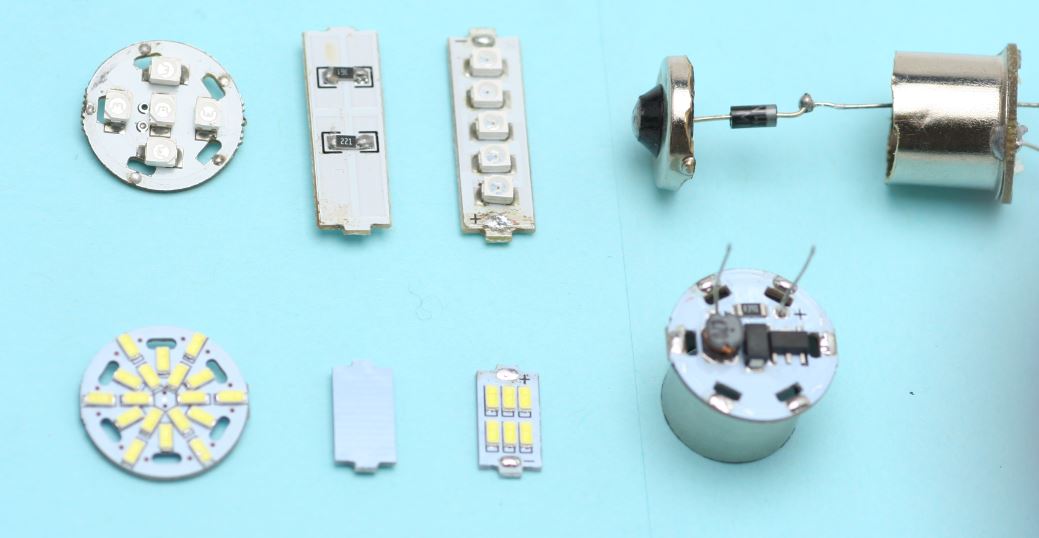
- LED_Comparison_1.JPG (51.21 KiB) Viewed 1706 times
Re: Electronic 2 Pin LED Flasher Test
Posted: Sat Jul 23, 2022 3:57 am
by mousewheels
Amber LED Schematic
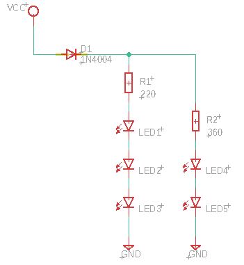
- Amber_LED_Panel_Schematic.JPG (17.56 KiB) Viewed 1706 times
White LED Component id
- Top - R390 -- 39 ohm resistor
- 9 o'clock 470 -- 47 uH inductor
- Center SS14 -- High speed switching diode
- 3 o'clock YDE8001A -- switching regulator IC -- data sheet not found
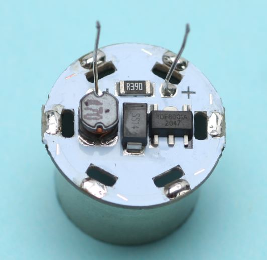
- White_LED_Driver_PCB_1.JPG (32.29 KiB) Viewed 1706 times
- Top -- Bridge Rectifier
- Bottom -- Capacitor
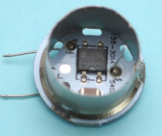
- LED_Driver_Board_1.JPG (31.14 KiB) Viewed 1706 times
Re: Electronic 2 Pin LED Flasher Test
Posted: Sat Jul 23, 2022 4:12 am
by mousewheels
Component ID T10 LED (the tiny Amber LED in prior photos)
PCB Top Side Components
- Top Left -- 1R00 -- 1 ohm resistor
- Top Center -- 4211 Switching regulator IC -- Datasheet found - sample schematic will follow
- Top Right -- 14A -- high speed switching diode
- Bottom components -- A7 -- general purpose diodes -- part of input bridge rectifier
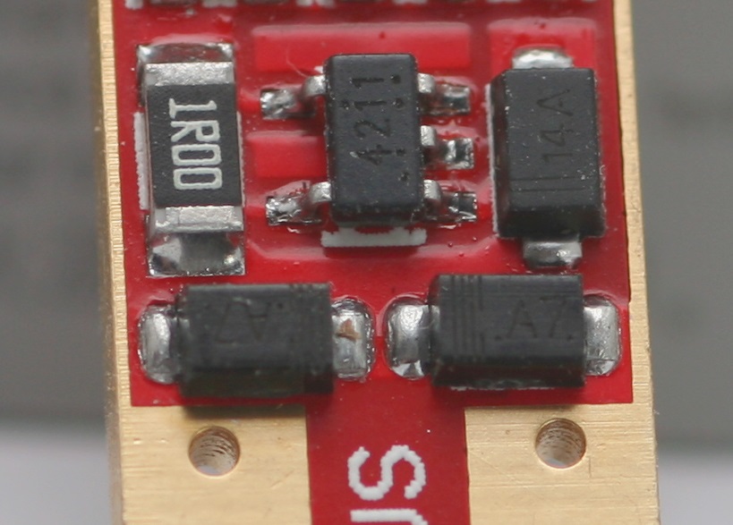
- Elite_Amber_LED_IC_Side.jpg (121.88 KiB) Viewed 1705 times
PCB Bottom Side Components
- Top Left -- 330 -- 33 uH inductor
- Top Right -- Ceramic capacitor
- Bottom components -- A7 -- general purpose diodes -- part of input bridge rectifier
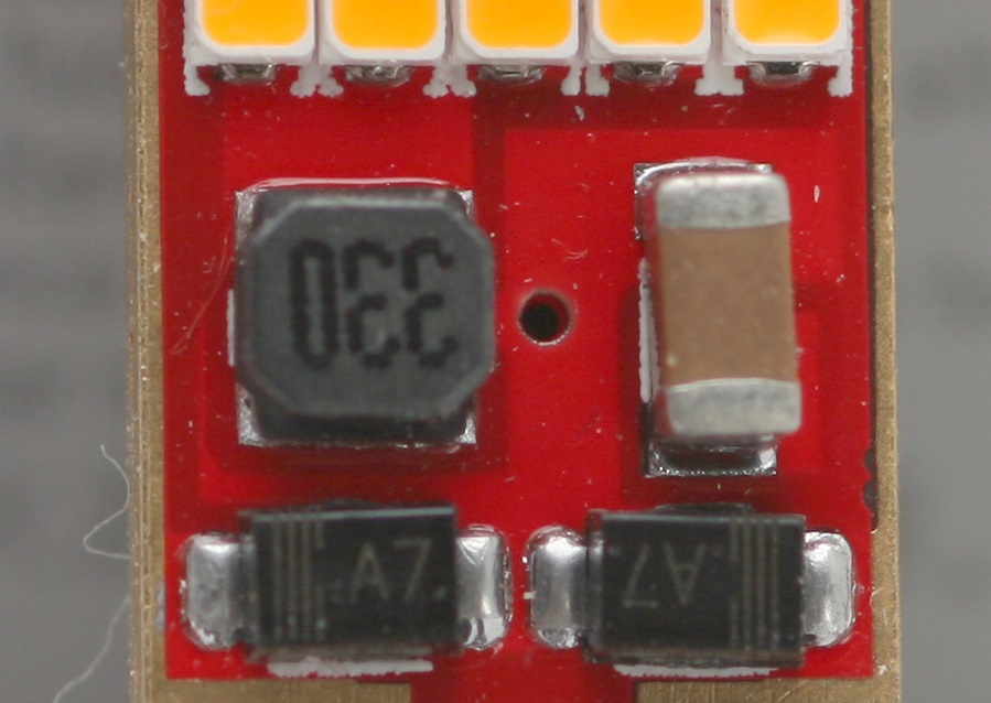
- Elite_Amber_LED_Inductor_Side.jpg (135.92 KiB) Viewed 1705 times
4211 Power supply IC typical application
The components on the LED have different values than the diagram. If interested search the 'net for the
full datasheet - there is some design info.
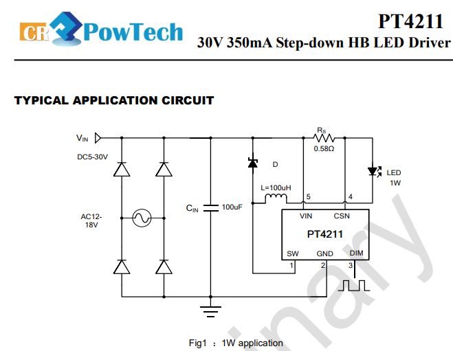
- PT4211_Typical_Circuit.JPG (44.27 KiB) Viewed 1705 times